Fiberglass Reinforced Plastic (FRP) Cable Tray
SFSP FRP Cable management System is manufactured under the brand name “Intech”, and is distributed exclusively by Unitech for Building and Construction Materials in the GCC and Mena regions. (FRP) Cable Management Systems are designed, manufactured, and tested to be installed in most harsh environmental conditions of onshore and offshore facilities for several industries including Oil and Gas, Petrochemicals, Manufacturing, Mining and others.

SFSP-INTECH Fiberglass Reinforced Plastic Cable Management System is designed, manufactured, and tested to be installed in most harsh environmental conditions of onshore and offshore facilities for several industries including Oil and Gas, Petrochemicals, Manufacturing, Mining and others.
- - FRP Cable Trays & Accessories
- - FRP Cable Ladder & Accessories
- - Related Hardware & Fittings
SFSP-INTECH Fiberglass Reinforced Plastic Cable Management System is available with a full range of fittings, splices, covers, accessories and support channels of cantilever and trapeze junctions. Our system is designed to fulfill the following standards’ requirements:
Specifications and Mechanical Performance:
- 1- NEMA FG-1:2002
- 2- UL 568:2019
Fire Performance:
- 1- BS 476 Part 7: 1997
- 2- ASTM E-84, Class 1: 2021
Installation:
- 1- NEMA VE2
- 2- NFPA 70:2023
Electrical Performance:
- 1- ASTM D149-20
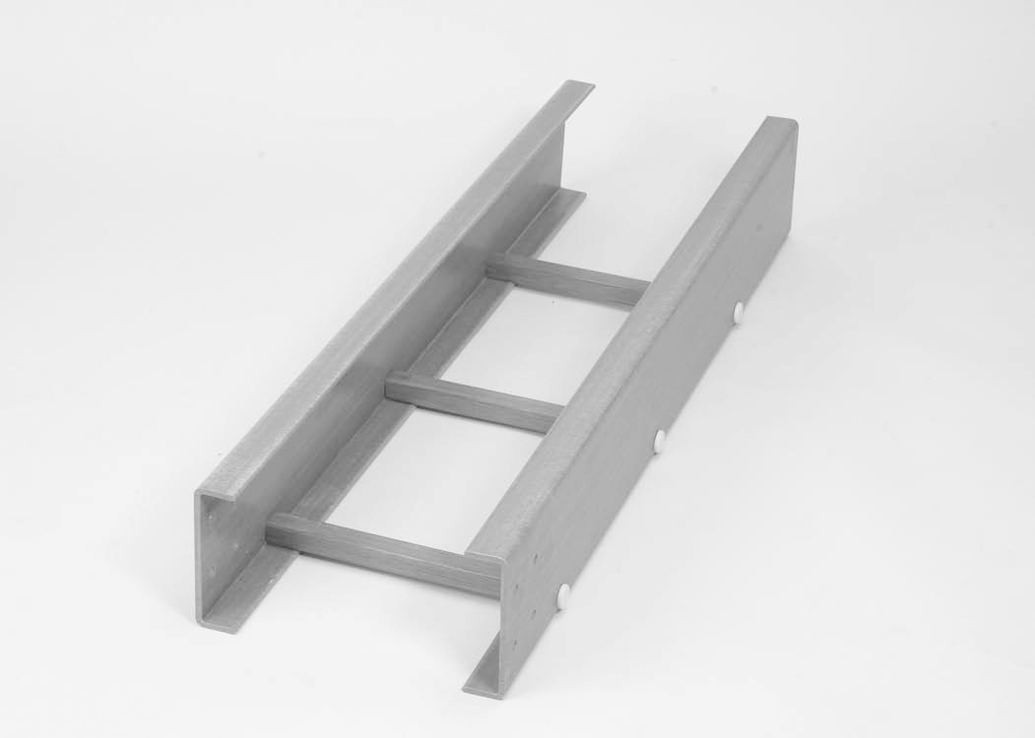
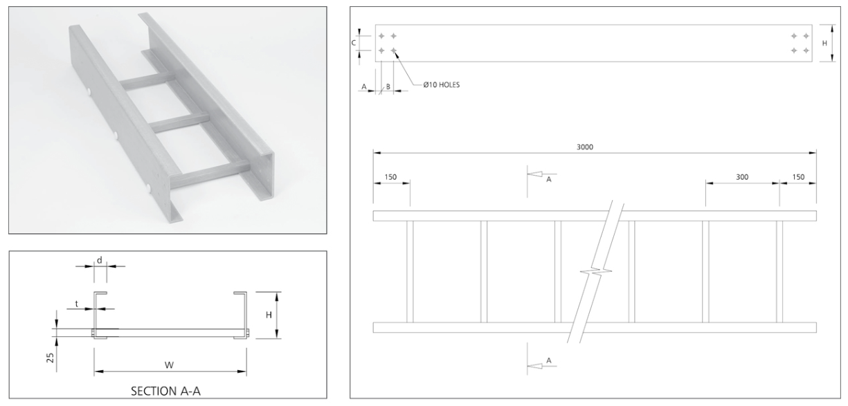
LH SERIES RUNS
- • Side Rail Height (H) : 102mm
- • Widths (W): 150mm, 300mm, 450mm, 600mm, 750mm, 900mm
- • Rung Spacing: 300 mm
- • Rung Dimensions: 25x25 mm
- • Standard Thickness: 4.8 mm
- • Standard Lengths (L) : 3000 mm
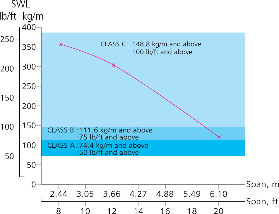
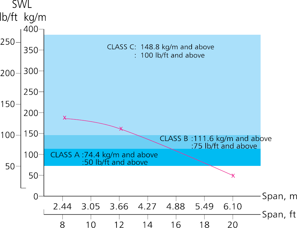
SAFE WORKING LOAD-CABLE LADDER
FRP Cable Ladder Load Test SFSP-INTECH LH Series, 152 Ht
| LH SERIES 152 HT |
Span (mm) | Class | Classification |
|---|---|---|---|
| 3000 | 8C | *NEMA FG1 20B |
|
| 3660 | 12C | ||
| 6096 | 20C |
| Item Code | Width | Height | Length | Thickness |
|---|---|---|---|---|
| mm | mm | m | mm | |
| SF-ITLH-SS-150-N | 150 | 152 | 3m | 6.0 |
| SF-ITLH-SS-300-N | 300 | 152 | 3m | 6.0 |
| SF-ITLH-SS-450-N | 450 | 152 | 3m | 6.0 |
| SF-ITLH-SS-600-N | 600 | 152 | 3m | 6.0 |
| SF-ITLH-SS-750-N | 750 | 152 | 3m | 6.0 |
| SF-ITLH-SS-900-N | 900 | 152 | 3m | 6.0 |
LH SERIES-STRAIGHT RUN
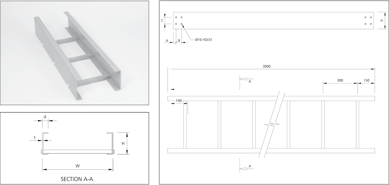
| TYPE | H | d | t | A | B | C | REMARKS |
|---|---|---|---|---|---|---|---|
| LH | 152 | 41 | 6.0 | 24 | 50 | 60 | W=150, 300, 450, 600, 750, 900 mm |
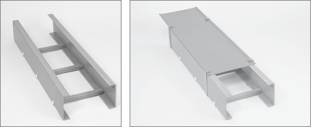
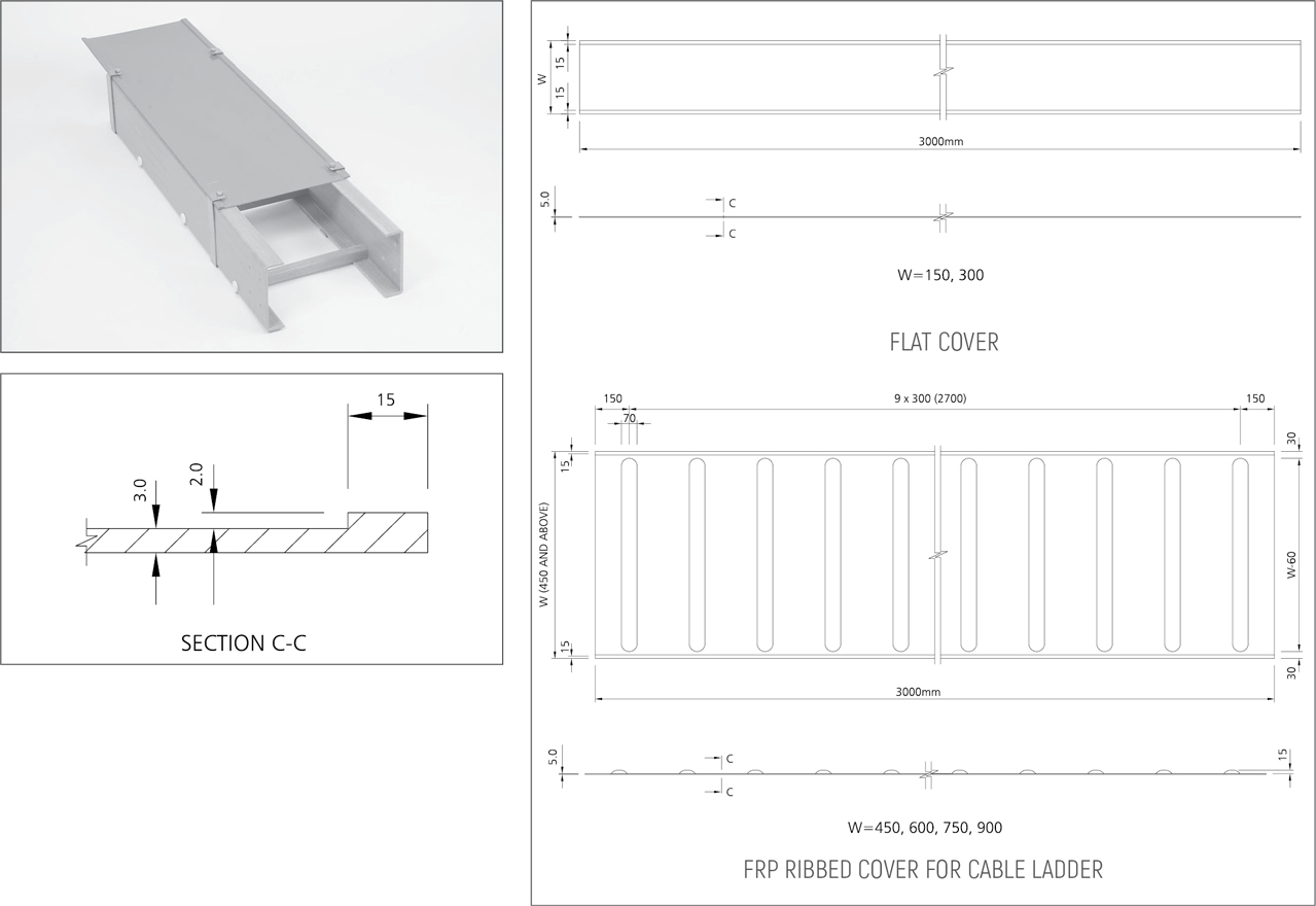
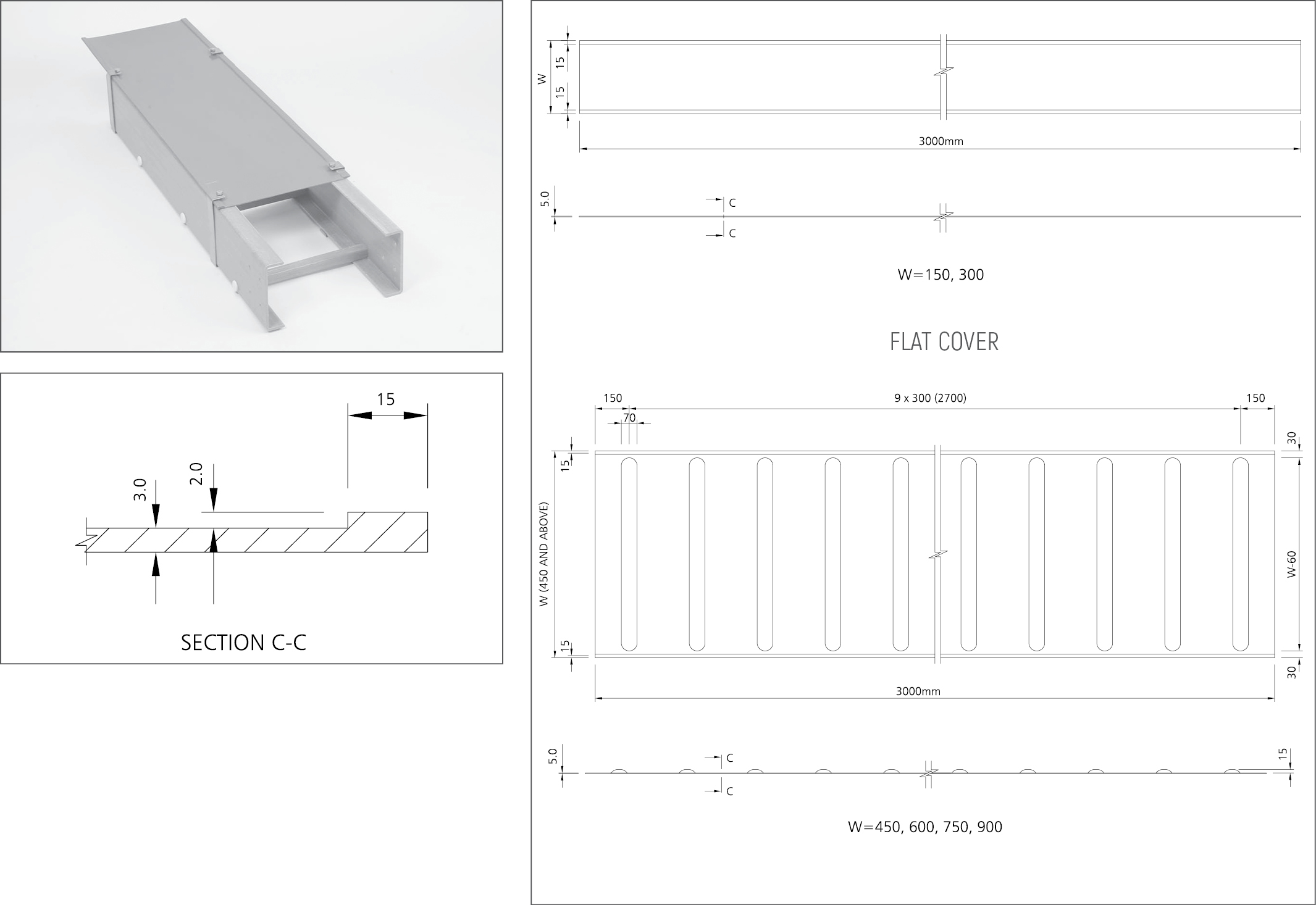
LH SERIES COVERS
Thickness of FRP side rail for LH Series is 6mm unless otherwise specified.
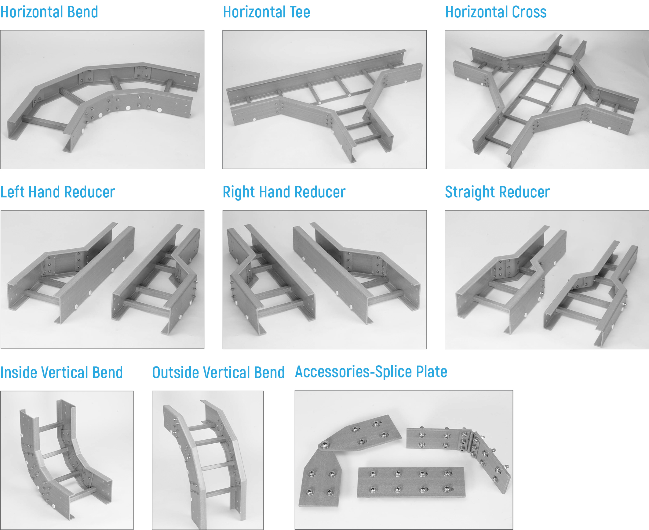
LH SERIES FITTINGS

LMH SERIES RUNS
- • Side Rail Height (H) : 102mm
- • Widths (W): 150mm, 300mm, 450mm, 600mm, 750mm, 900mm
- • Rung Spacing: 300 mm
- • Rung Dimensions: 25x25 mm
- • Standard Thickness: 4.8 mm
- • Standard Lengths (L) : 3000 mm

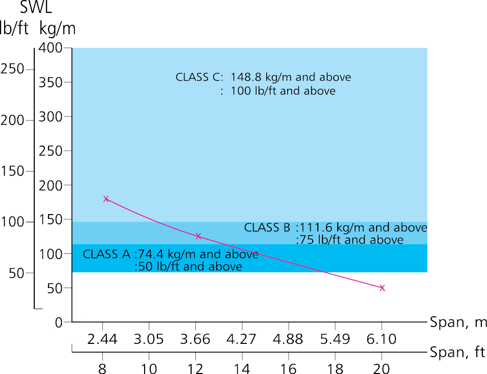
SAFE WORKING LOAD-CABLE LADDER
FRP Cable Ladder Load Test SFSP-INTECH LMH Series, 152 Ht
| LMH SERIES 152 HT |
Span, ft | Class | Classification |
|---|---|---|---|
| 3000 | 8C | *NEMA FG1 12C |
|
| 3660 | 12C | ||
| 6096 | 20A |
| Item Code | Width | Height | Length | Thickness |
|---|---|---|---|---|
| mm | mm | m | mm | |
| SF-ITLMH-SS-150-N | 150 | 152 | 3m | 6.0 |
| SF-ITLMH-SS-300-N | 300 | 152 | 3m | 6.0 |
| SF-ITLMH-SS-450-N | 450 | 152 | 3m | 6.0 |
| SF-ITLMH-SS-600-N | 600 | 152 | 3m | 6.0 |
| SF-ITLMH-SS-750-N | 750 | 152 | 3m | 6.0 |
| SF-ITLMH-SS-900-N | 900 | 152 | 3m | 6.0 |
LMH Series-Straight Run

| TYPE | H | d | t | A | B | C | REMARKS |
|---|---|---|---|---|---|---|---|
| LMH | 152 | 41 | 4.5 | 24 | 50 | 60 | W=150, 300, 450, 600, 750, 900 mm |
LMH Series-Cover
Thickness of FRP side rail for LMH Series is 4.5 mm unless otherwise specified.
LMH SERIES FITTINGS

LM SERIES
- • Side Rail Height (H) : 102mm
- • Widths (W): 150mm, 300mm, 450mm, 600mm, 750mm, 900mm
- • Rung Spacing: 300 mm
- • Rung Dimensions: 25x25 mm
- • Standard Thickness: 4.8 mm
- • Standard Lengths (L) : 3000 mm

SAFE WORKING LOAD-CABLE LADDER
FRP Cable Ladder Load Test SFSP-INTECH LM Series, 102 Ht
| LM SERIES 102 HT |
Span, ft | Class | Classification |
|---|---|---|---|
| 3000 | 8C | *NEMA FG1 12B |
|
| 3660 | 12C | ||
| 6096 | 20A |
| Item Code | Width | Height | Length | Thickness |
|---|---|---|---|---|
| mm | mm | m | mm | |
| SF-ITLM-SS-150-N | 150 | 102 | 3m | 6.0 |
| SF-ITLM-SS-300-N | 300 | 102 | 3m | 6.0 |
| SF-ITLM-SS-450-N | 450 | 102 | 3m | 6.0 |
| SF-ITLM-SS-600-N | 600 | 102 | 3m | 6.0 |
| SF-ITLM-SS-750-N | 750 | 102 | 3m | 6.0 |
| SF-ITLM-SS-900-N | 900 | 102 | 3m | 6.0 |
LM SERIES-STRAIGHT RUN
| TYPE | H | d | t | A | B | C | REMARKS |
|---|---|---|---|---|---|---|---|
| LM | 101 | 41 | 4.8 | 24 | 50 | 60 | W=150, 300, 450, 600, 750, 900 mm |
| TYPE | H | d | t | A | B | C | REMARKS |
|---|---|---|---|---|---|---|---|
| LMH | 152 | 41 | 4.5 | 24 | 50 | 60 | W=150, 300, 450, 600, 750, 900 mm |
LH SERIES-COVER
Thickness of FRP side rail for LM Series is 4.5 mm unless otherwise specified.
LM SERIES FITTINGS
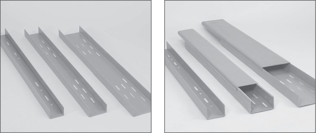
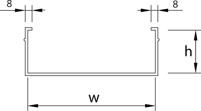
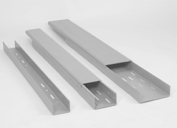
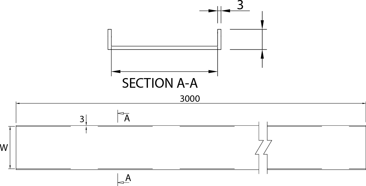
TYPES C & U SERIES
- • Side Rail Height (H) : 50mm
- • Widths (W) : 50mm, 75mm, 100mm, 150mm, 200mm, 300mm, 400mm, 600mm
- • Standard Slot : 7.5 x 50 mm
- • Standard Lengths (L) : 3000 mm
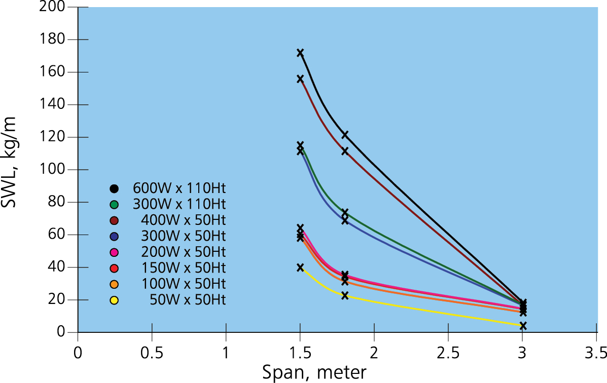
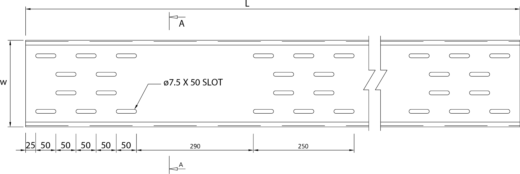
| Item Code | Width | Height | Length | Thickness | Safe Working Load for Span 1500 |
|---|---|---|---|---|---|
| mm | mm | mm | mm | kg/m | |
| SF - ITCT50-SS-100-P | 50 | 50 | 3M | 3 | 39.5 |
| SF - ITCT50-SS-150-P | 75 | 50 | 3M | 3 | 57.9 |
| SF - ITCT50-SS-200-P | 100 | 50 | 3M | 3 | 60.2 |
| SF - ITCT50-SS-300-P | 150 | 50 | 3M | 3 | 63.8 |
| SF - ITCT50-SS-400-P | 200 | 50 | 3M | 3 | 111.1 |
| SF - ITCT110-SS-150-P | 300 | 50 | 3M | 3 | 114.7 |
| SF - ITCT110-SS-200-P | 400 | 50 | 3M | 3 | 155.6 |
| SF - ITCT110-SS-300-P | 600 | 50 | 3M | 3 | 171.5 |
| SF - ITCT110-SS-450-P | 300 | 110 | 3M | 3 | 141.4 |
| SF - ITCT110-SS-600-P | 600 | 110 | 3M | 3 | 197.1 |
CABLE TRAY-C SERIES & U SERIES-COVER
| ITEM CODE | W | H |
|---|---|---|
| SF-1022-CO-050 | 50 | 10 |
| SF-1022-CO-070 | 75 | 15 |
| SF-1022-CO-100 | 100 | 15 |
| SF-1022-CO-150 | 150 | 18 |
| SF-1022-CO-200 | 200 | 18 |
| SF-1022-CO-300 | 300 | 18 |
| SF-1022-CO-400 | 400 | 18 |
| SF-1022-CO-600 | 600 | 18 |
TYPES C & U SERIES FITTINGS

Benefits of INTECH FRP Pultruded and Molded Grating
Corrosion Resistance
No rusting, peeling or flaking, even under the most aggressive conditions in any part of the world.
Lightweight and Durable
Lightweight of FRP ease handling and cutting, reduce size of platform structure.
Cost Effective
Extremely long life compared to metal and others plastic, “with no maintenance required.”
High Strength and Stiffness
High glass content and continuous reinforcement, pultruded FRP products give extremely high strength and stiffness compared to other engineering plastic.
High Impact Resistance & Elastic
Returns to original position without any permanent deflection or distortion with allowable loads.
Superior Weatherability
SFSP / INTECH’s integral UV protection system gives long term protection against UV attack.
Non-Conductive & Non-Interfering
Complies to international electrical safety specification and transparent to radio waves and is nonmagnetic.
Low Thermal Conductivity & Expansion Rate
Will not transfer heat, and no problem of expansion under heat.
Fire Retardant
Fire retardant quality is available with compliance to ASTM-E84 and BS 476 standards.
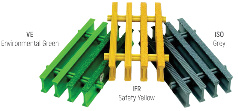
Standard Colour Code :
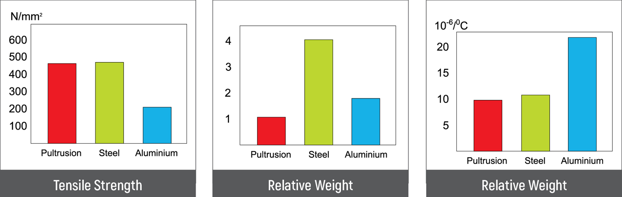
Typical Properties of Pultrusion FRP Products
- The information given below is a guide to the typical properties of Pultruded Fiberglass Reinforced plastic. The pultruded profiles are made from a combination of continuous Longitudinal Rovings, Continuous Filament Mats and Resin, thus properties will vary depending on reinforcement and resin choice.
Comparison
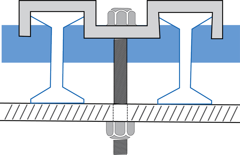
Installation System
M-CLIP
M-Clip is used to secure panels by drilling through the support structures. It is designed to use two adjacent grating bars for a more secure fit.
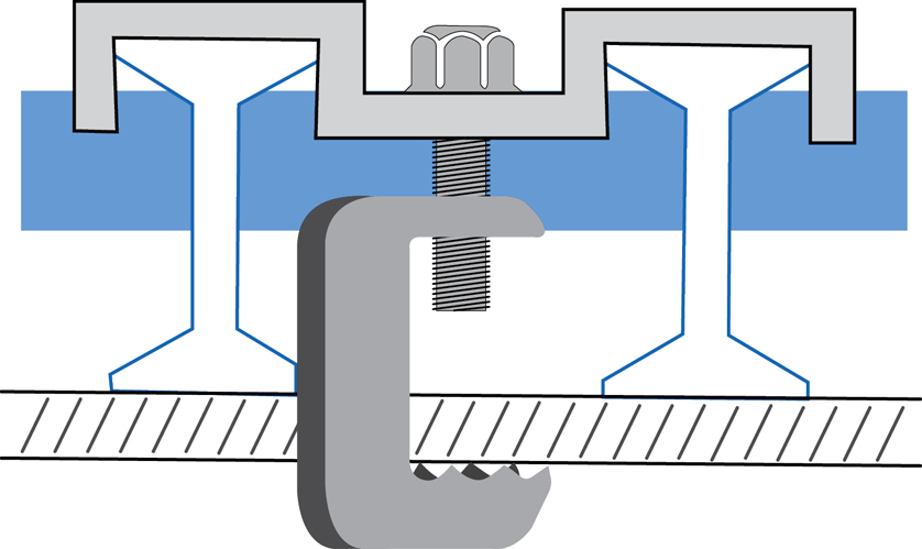
G-CLIP
G-Clip is designed to attach grating to any structural support, with no drilling required. Recommended for offshore projects.
Fiberglass Reinforced Plastic
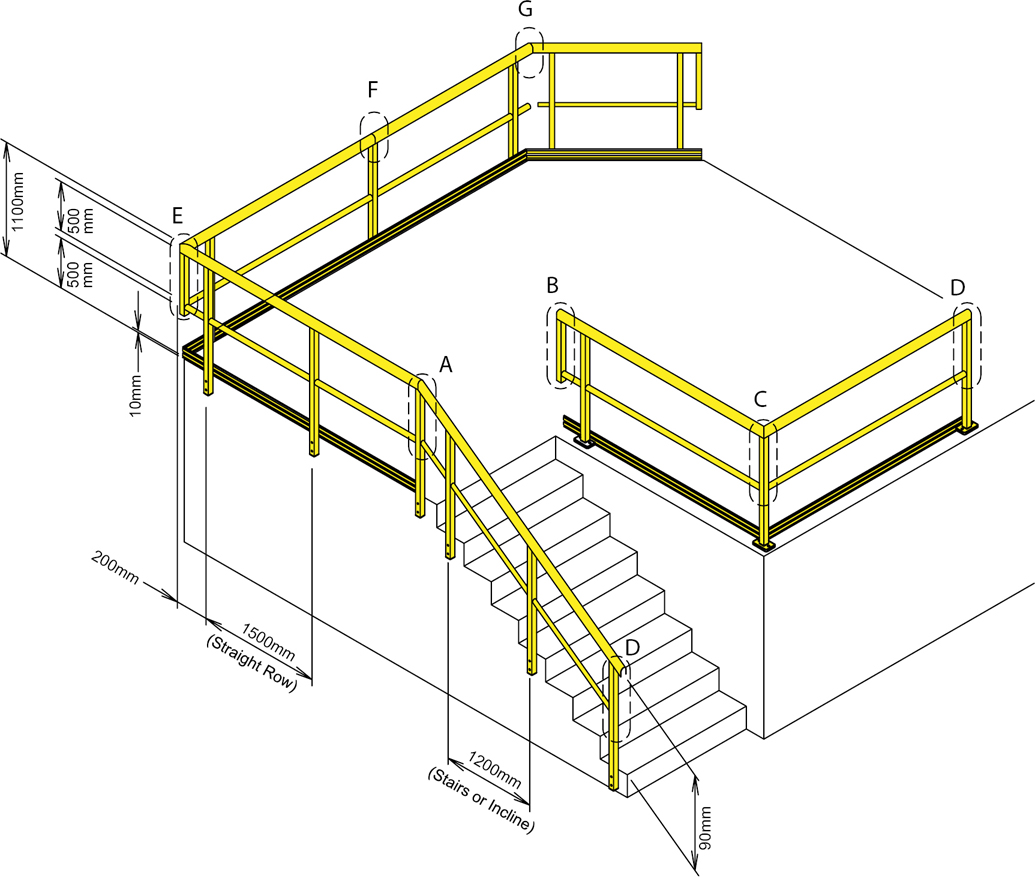
- SFSP - INTECH FRP handrail is constructed in several models using structural profiles such as square hollow section, round tube and others.
- Unlike other steel or aluminium handrail, the FRP handrail offers several advantages such as corrosion resistance, long service life, cost effective, lightweight and high strength, ultimate UV protection, and others. It has been widely used in offshore construction, oil & gas industry, ship building and marine industry, and etc where corrosion and UV protection are the main concerned.
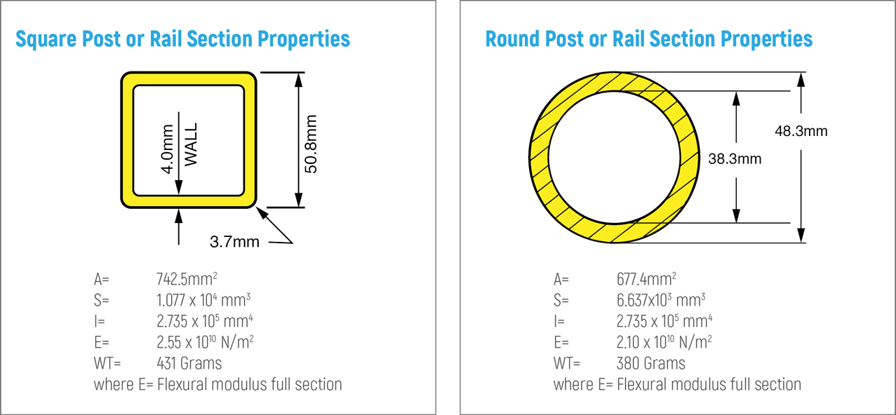
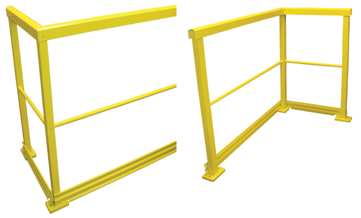
Typical Square Handrail Construction
Typical Round Handrail Construction
Round Handrail System
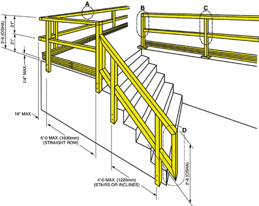
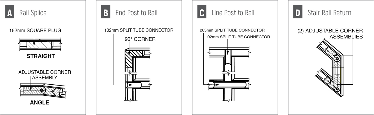
The round handrail system is a round fiberglass system that is ideal for any high traffic area where handrail is needed. The round rails are easy to grip and 90o molded corners eliminate sharp edges. The handrail system meets OSHA strength requirements with a 2:1 factor of safety with a 1524mm maximum post spacing. The handrail system can be made to comply with ADA standards upon request. Internally bonded fiberglass connectors result in no visible rivets or metal parts. Rail and posts are 48.3mm O.D. x 38.3mm I.D. This is the same outside dimension as typical metal rails for ease of adapting to common metal brackets. Kickplates are available upon request. The round handrail system is pultruded using either a vinyl ester or a polyester resin system. The handrail system includes a UV inhibitor for additional resistance to ultraviolet degradation and corrosion.
Typical applications include:
- • Food Processing Facilities
- • Platforms & Walkways
- • HEAVY INDUSTRIAL PLANTS
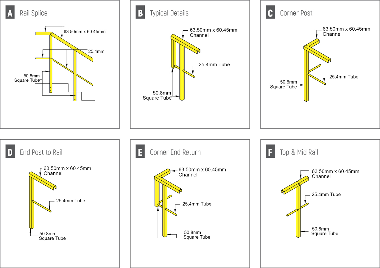
Channel Top Handrail System
The channel top industrial fiberglass handrail is an economical commercial railing system designed for long runs on platforms and walkways. The railing system is designed for fabrication efficiency and is not particularly well-suited for stair rails with twists and turns. The channel top can be used in combination with round and square as needed. The channel top systems are fabricated as handrails and guardrails using pultruded fiberglass components produced by Strongwell and molded thermoplastic connectors. The channel top system consists of a 63.50mm x 60.45mm channel top rail, 50.80mm x 50.80mm x 3.96mm square tube posts and a 1” inch diameter round tube mid rail.
Advantages:
- The benefits to designing a channel top fiberglass handrail system are:
- • Easy installation and field fabrication
- • Economical installation of long straight runs
- • Fewer components, reducing freight cost
- • No epoxy required
- • All riveted connections
- In addition, channel top shares same benefits and advantages of the original such as:
- • Corrosion resistance
- • Strength
- • Impact resistance
- • Light weight
- • Low thermal conductivity
- • Low electrical conductivity
- Standard channel top handrail systems are pultruded using a polyester, fire-retardant resin system. The handrail system includes a UV inhibitor for additional resistance to ultraviolet degradation and corrosion. Standard color is yellow, however, other colors are available upon request.
-
Safety:
- The channel top handrail system meets osha strength requirements. It has also been independently tested and meets the british standard en iso 14122-3:2001 require-ments. The handrail system sustained a falling weighted bag impact force of 216.5 Ft-lb (293.6 N-m).
Typical Square Handrail Construction
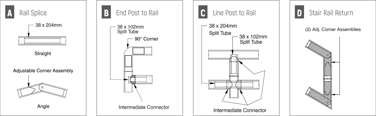
Typical Details
Warning: include(/home/site/wwwroot/includes/mep-solutions-menu.php): Failed to open stream: No such file or directory in /home/site/wwwroot/products/steel-construction-products/mechanical-electrical-plumbing-solutions/cable-management-systems/frp-cable-tray.php on line 1611
Warning: include(): Failed opening '/home/site/wwwroot/includes/mep-solutions-menu.php' for inclusion (include_path='.:/usr/local/lib/php') in /home/site/wwwroot/products/steel-construction-products/mechanical-electrical-plumbing-solutions/cable-management-systems/frp-cable-tray.php on line 1611